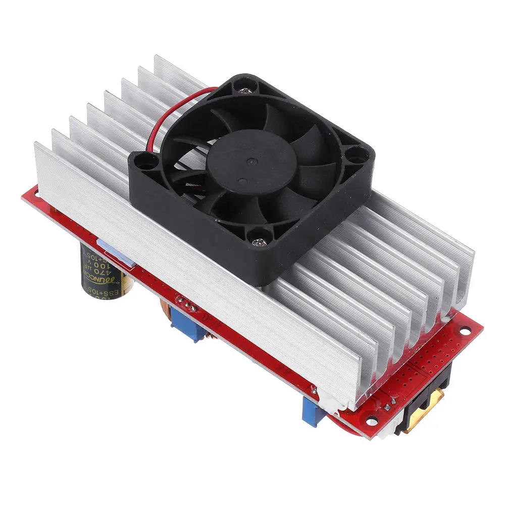
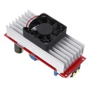
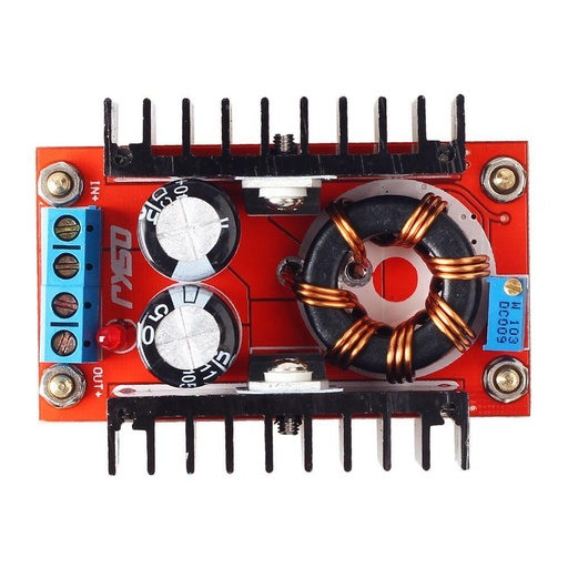
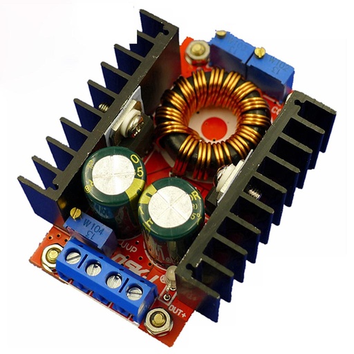
With airfoil with airfoil, the heat dissipation effect is very good, and the output power is larger (the power can be up to 1200W when 48V input and fan are added).
The temperature-controlled fan, combined with the hydraulic bearing fan, achieves a very good balance between noise and heat dissipation. When the load is light, the fan does not rotate, and the fan automatically turns on after the load weight reaches 60 degrees. Can effectively reduce noise and extend life.
The main power tube insulation board is made of high-grade alumina, and the thermal conductivity is 10 times that of ordinary insulation pads.
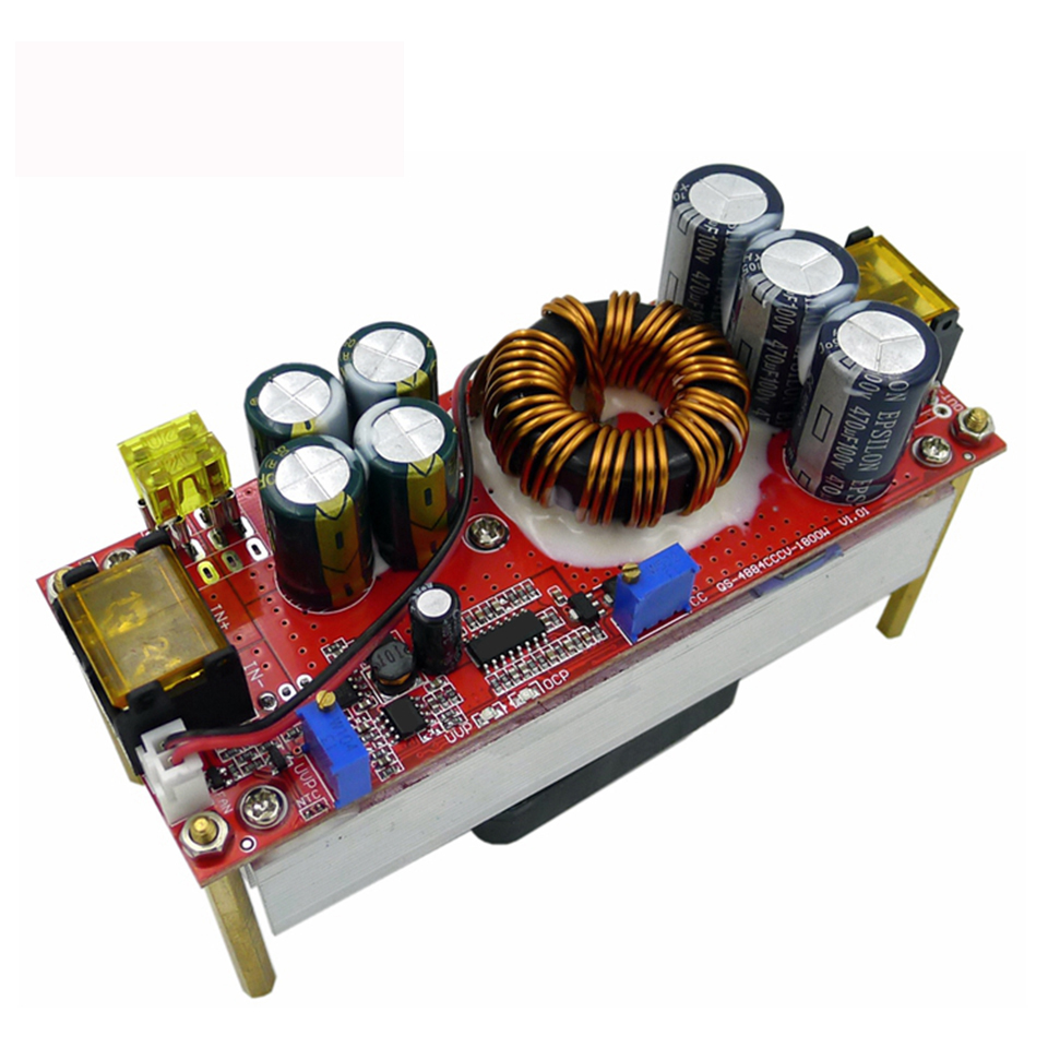
Adopt 100V 210A TO-247 large package power tube, with large power margin and good dynamic response.
Large-size iron-silicon-aluminum magnetic ring, using 3 1.2 pure copper enamel enveloping lines, low heat and high efficiency.
New design, conversion efficiency of up to 98.1% (see the data sheet efficiency conversion curve below for details).
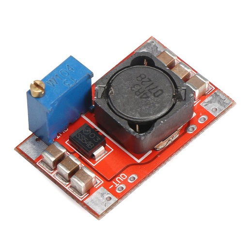
The brand 3296W multi-turn potentiometer has high adjustment precision and small drift.
Constant copper wire output current sampling, constant current stable temperature drift small.
The undervoltage protection is adjustable, which can effectively protect various batteries and can also be used for solar cells.
With constant current function, it can be used for battery car boost, battery charging and so on.
Input two 20A fuses in parallel to protect the risk of accidental short circuit output.
Three indicators: undervoltage, overcurrent, power indication, working status at a glance.
Both input and output use high frequency capacitors, low output ripple, low heat generation and long life.
The input and output have newly added MLCC ceramic capacitors, and the output ripple is significantly reduced. It is about 100 millivolts at 48V to 72V 4A.
Enter low battery protection adjustment:
Low battery protection is mainly to prevent over-discharge of the battery when the input power is the battery. The battery voltage is too low to damage the power module and the battery. When the input is a switching power supply, the low voltage protection should also be set.
Method 1: For example, set 12V battery low battery protection. Connect a voltage of 11V to the input terminal of the power module. Use a flat-blade screwdriver to adjust RV1 (clockwise protection voltage value is increased, counterclockwise protection voltage is turned down) until the UVLO lamp is on. At this time, the low battery protection voltage is 11V. When the voltage drops to 11V, the power module does not rise (the input voltage is equal to the output voltage). Only after the input voltage is higher than 11V, the power supply starts to resume boosting.
Method 2: Input the battery or switch power supply. If the UVLO lamp on the board is off, adjust the RV1 potentiometer clockwise, brighten the UVLO lamp, and then turn it clockwise two turns. If the UVLO lamp is on, turn the RV1 potentiometer counterclockwise, turn off the UVLO lamp, and then turn it two turns. (Adapt to 10V-45V voltage)
Precautions:
(1) The output positive and negative poles cannot be reversed and cannot be short-circuited.
(2) If used for electric vehicle boost drive power supply, the input voltage must be 24V or more. The electric vehicle power is less than 500W. Because the electric motor is an inductive load, the current will be large at the moment of starting and uphill. There must be sufficient power headroom.
(3) When using batteries, switching power supplies, solar panels, generators, etc. as input sources, battery protection must be lowered, otherwise the battery and power supply may be damaged.
(4) Pay attention to ventilation and heat dissipation when working for a long time, high current, high power and full load, in order to extend the service life of the power supply.
(5) The module can only boost the voltage and cannot supply voltage to the electrical equipment below the input voltage. For example, charge the 12V battery with a 24V battery or charge the capacitor. Powering the lED below the input voltage
(6) Do not work at full load for a long time. Please keep 20% margin when working continuously, pay attention to ventilation and heat dissipation.
Common problem:
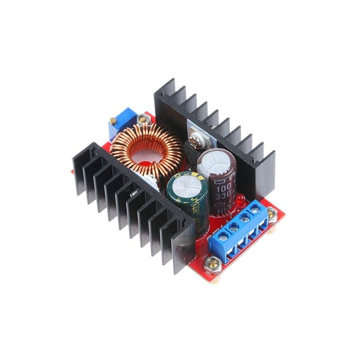
1. Q: Why is this shape designed?
A: This module is designed for your convenience and is fixed directly on the machine. You can fix the module on your machine with 4 copper posts.
2.Q: How efficient is the module? Can I use it on a battery which needs high efficiency? Can it be used?
A: The working efficiency of this module is very high. The actual test rate can reach 98.1%.
3.Q: Is this power module short-circuit protected? When I use it, I accidentally output a short circuit and it will burn out?
A: This module is short-circuit protected. When your output is short-circuited, the fuse will blow and you need to replace the fuse to recover. Therefore, you need to pay attention to when using, try not to short circuit.
4.Q: Does this power module have input reverse connection protection? When I use it, I accidentally input the power supply and it will burn out when I reverse it.
A: It won't burn out. This module is equipped with reverse connection protection.
5.Q: The working voltage of the module is 10-60V, then can I output 48V by inputting 12V?
A: Yes. This module is a boost module.
6.Q: Can this module current run at 72V 10A for a long time?
A: This module has a design power of 1800W and can run at 1500W for a long time (requires fan forced cooling), 72V*10A=720W, so it can run for a long time.
7.Q: I need about 20A current. Can this module work in parallel?
Answer: When the input power is separately supplied, the output can be directly connected in parallel and the power is doubled. When the input is connected to the same power supply, it is not possible.
8.Q: What is the working environment temperature of this module, can it reach the industrial level?
A: Yes, but when the ambient temperature exceeds 40 degrees, please reduce power usage or enhance heat dissipation.
9.Q: I think your module has a potentiometer on it. Will the output voltage suddenly rise due to potentiometer damage?
A: No, the multi-turn precision potentiometer is used on the module. His adjustment accuracy and reliability are very high, and there is no sudden increase in output voltage. You can use it with confidence. It is also recommended that bulk customers find us to customize the fixed output voltage.
10.Q: I think your module power is 1800W. If I output 60V, what should the current be?
A: This can be calculated by the formula P=U*I, I=P/U, the output voltage is 60V, and the current is 30A. Since the module output current is about 22A, the output current is 22A.
11.Q: The working voltage of the module is 10-60V, then can I input 97V 1800W by inputting 12V?
A: No. Input 12V can output 97V, but if you want to output 1800W power input voltage must be above 48V.