DC-DC Converter 1800W 30A CC CV Step up Power Supply Module QS-4884CCCV-1800W

Price:

1.94


9W High Power Imitation Lumen RGB Led Four Feet
1.10
1.10
4.8/6.3MM Plug Spring Insulated Terminal Cold Terminal Crimp Terminal 10CM/20CM
0.50
0.50

DC-DC Converter 1800W 30A CC CV Step up Power Supply Module QS-4884CCCV-1800W

https://www.satisled.com/web/image/product.template/6704/image_1920?unique=9cde222
(0 review)

18.12 18.12 USD 18.12

¥ 131.00

Not Available For Sale


    This combination does not exist.


    SKU :
    1941708
    Share :
    100% original guarantee
    Return within 30days
    Free delivery on all orders

    Brand: QSKJ

    Model:  QS-4884CCCV-1800W

    Features:

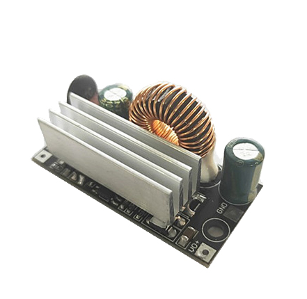
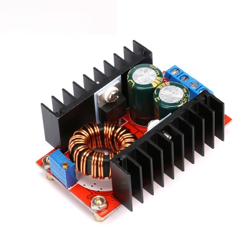
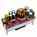
    • With the airfoil, the heat dissipation is very good, the output power is greater (48V input plus fan power can be around 1800W when the fan is added).

    • The temperature control fan, combined with the hydraulic bearing fan, is well balanced on the noise and heat dissipation. When the load is light, the fan does not rotate, and the load temperature reaches about 60 degrees, and the fan automatically turns. It can effectively reduce noise and prolong life.

    • The main power pipe insulation board uses high grade alumina, and the thermal conductivity is 10 times as high as the ordinary insulation pad.

    • Using 100V 210A TO-247 large package power tube, the power allowance is large and the dynamic response is good.

    • The double large size iron silicon aluminum magnetic ring, 4 1.2 pure copper enameled wire and Rao, low heat, high efficiency.

    • New design, the conversion efficiency is up to 98.1% (for details see the efficiency conversion curve of the following data handbook).

    • The brand 3296W multi loop potentiometer has high adjustment precision and small drift.

    • Kang Tong wire output current sampling, constant current steady temperature drift small.

    • Undervoltage protection is adjustable, it can effectively protect all kinds of batteries, and can also be used in solar cells.

    • With constant current function, it can be used to boost the battery car, charge the battery and so on.

    • 3 20A fuse are connected in parallel, which can protect the risk of accidental short circuit of output.

    • Three indicator lights: undervoltage, over current, power indicator, working state at a glance.

    • High frequency capacitance is used in both input and output. The output ripple is low, heat is small, and the life is long.

    • The MLCC ceramic capacitor is added to the input and output, the output ripple is obviously reduced, and about 100 mV at the time of 48V to 72V 4A.

    Application scope:

    • QS-4884CCCV-1800W is designed for lead-acid batteries, lithium batteries, solar cells or power booster to boost electric vehicles, battery charging, and has powerful functions.

    • For example, the original battery of the electric car is 48V can be boosted to 60V to power the electric vehicle, which can improve the speed and acceleration of the electric vehicle.

    • Charge for your electric bicycle. (1: for example, if you have a 12V or 24 idle battery on your hand, you can charge the battery by boosting the power supply, which is equivalent to an electric vehicle's charging treasure. Two: at the same time input can also be connected to solar cells, wind, generator and other power supplies to the original battery charging to increase the endurance of the electric vehicle.)

    • Can increase the battery voltage to make the electric car run faster, not more than 10V.

    • Solar panels are boosted and regulated.

    Appearance size:

    • 130 (L) *51 (W) *80 (high water column) mm

    • 4 3*50mm  long fixed pillars

    Pin mode:

    • IN input cathode, anode, cathode OUT IN input output, OUT negative output

    • CV voltage regulation, CC current regulation, UVP input under voltage protection regulation

    Operation guide:
     
    Voltage regulation:
    When the power supply is unloaded, use a flat-blade screwdriver to adjust the output terminal "V-ADJ" potentiometer (marked in the figure below) to increase clockwise and counterclockwise to adjust). Because the output capacitor capacity is large, the output voltage is When the high voltage is adjusted to a low voltage, the reaction will be slower. The adjustment of the instrument is smaller.
     
    Current regulation:
    Adjust the "CC A-ADJ" potentiometer counterclockwise for about 30 turns, set the output current to the minimum, connect the load such as the LED battery, and adjust the "CC A-ADJ" potentiometer clockwise to the current you need. For battery charging, after the battery is discharged, it is connected to the output, and adjust the CC A-ADJ to the current you need. When charging, be sure to use the discharged battery to adjust the battery. The more the charge, the smaller the charge current. The default output ESC is shipped to 10A. If we need to adjust the current value of the instructions or message. Do not use the short-circuit output to adjust the current, the circuit structure of the boost module can not be adjusted by short circuit.
     
    Enter low battery protection adjustment:
     
         Low battery protection is mainly to prevent over-discharge of the battery when the input power is the battery. The battery voltage is too low to damage the power module and the battery. When the input is a switching power supply, the low voltage protection should also be set.
     
         Method 1: For example, set 12V battery low battery protection. Connect a voltage of 11V to the input terminal of the power module. Use a flat-blade screwdriver to adjust RV1 (clockwise protection voltage value is increased, counterclockwise protection voltage is turned down) until the UVLO lamp is on. At this time, the low battery protection voltage is 11V. When the voltage drops to 11V, the power module does not rise (the input voltage is equal to the output voltage). Only after the input voltage is higher than 11V, the power supply starts to resume boosting.
     
         Method 2: Input the battery or switch power supply. If the UVLO lamp on the board is off, adjust the RV1 potentiometer clockwise, brighten the UVLO lamp, and then turn it clockwise two turns. If the UVLO lamp is on, turn the RV1 potentiometer counterclockwise, turn off the UVLO lamp, and then turn it two turns. (Adapt to 10V-45V voltage)
     
     
    Precautions:
     
    (1) The output positive and negative poles cannot be reversed and cannot be short-circuited.
    (2) If used for electric vehicle boost drive power supply, the input voltage must be 24V or more. The electric vehicle power is less than 500W. Because the electric motor is an inductive load, the current will be large at the moment of starting and uphill. There must be sufficient power headroom.
    (3) When using batteries, switching power supplies, solar panels, generators, etc. as input sources, battery protection must be lowered, otherwise the battery and power supply may be damaged.
    (4) Pay attention to ventilation and heat dissipation when working for a long time, high current, high power and full load, in order to extend the service life of the power supply.
    (5) The module can only boost the voltage and cannot supply voltage to the electrical equipment below the input voltage. For example, charge the 12V battery with a 24V battery or charge the capacitor. Powering the lED below the input voltage
    (6) Do not work at full load for a long time. Please keep 20% margin when working continuously, pay attention to ventilation and heat dissipation.